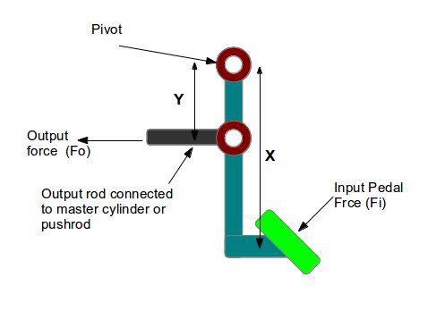
The clutch or brake pedal of a car is an example of either a first or a second class mechanical lever depending upon the design of the pedal.

The pedal ratio or the mechanical advantage is the ratio of the output force (Fo) to the input force (Fi) or the ratio of input lever length (X) and output lever length (Y):
Pedal ratio or mechanical advantage= Fo / Fi = X/Y…………………………….eq.1
What is the importance of the ratio for automotive braking system design calculation?
We can conclude, from the eq.1 above, that increase in the ratio means:
- More output force for less pedal force – which is good from user comfort.
- And, at the same time, longer input arm (X) – which means more input pedal travel- which is not good since user has to press the brake pedal for longer travel distance. Also, the increased input arm length will definitely make you, the designer, unhappy as it will require more packaging space. Another worry for the designer, in case of longer input arm, is its strength – as the length of the input arm increases – its overhang increases which means you have to think about making it stronger by adding some gussets or y some other means.
- However, there is another way of increasing the ratio without increasing the input arm length (X) and that is by decreasing the output arm length (Y), of course, if your design has scope for that- because, the output arm may already be short and you may not be able to reduce it further.
Typically, the pedal ratio lies between 4:1 to 6:1. Power brake requires lower ratio and manual hydraulic system require higher ratio.
What is a variable ratio pedal?
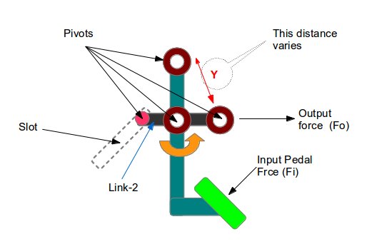
As the name suggests, in case of a variable ratio, the brake (or clutch) pedal ratio changes as the driver presses the brake padel. How? See the below figure of a VR pedal:

The output pivot is no more a fixed one, rather it is at the end of the link-2, the other end of the link-2 follows the slot. As a result, with the depression of the pedal, the output pivot point comes closer to the main pivot and thus the length of the output arm (Y) reduces and causes the overall leverage ratio to increase.
What it means to the driver is: at the end of the pedal stroke the driver needs to press the pedal less harder which in-turns will increase the drivers operational comfort because towards the end of the pedal stroke, normally, the braking system (or clutch system) demands more force.
Hi, I am Shibashis, a blogger by passion and an engineer by profession. I have written most of the articles for mechGuru.com. For more than a decades i am closely associated with the engineering design/manufacturing simulation technologies. I am a self taught code hobbyist, presently in love with Python (Open CV / ML / Data Science /AWS -3000+ lines, 400+ hrs. )

Nice Post
Now a days in car there are different variation in break.
http://www.premierautoofswfl.com