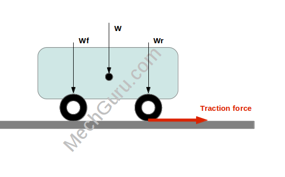
Tractive force or tractive effort or traction is the force applied between the tire and road surface to move a car or any vehicle for that matter.
The maximum permissible traction force that can be applied to the wheels is governed by two things: the weight of the vehicle and the adhesion coefficient between the tire and the road surface.
More the weight and the adhesion coefficient more amount of tractive force can be applied to the wheels without causing slips between the tires and road.

You might have seen in movies that before the starts of the car racing smokes come out as a result of friction between high speed tire rubber and road, this is because the driver accelerate the engine too much to cross the maximum permissible traction force limit and which in turns permit the wheels to slip burn the rubber to cause the fumes.
Tractive Force Calculation for a Vehicle : Applied tractive force based on engine torque can be calculated as
TE = (Et x η x Ng x Na ) / R…………………………eq.1
Where,
TE – tractive force in N
Et – Engine torque in Nm
η – Overall efficiency of power train
Ng – Transmission ratio
Na – Driving axle ratio
R – Tire rolling radius
Calculation of maximum permissible traction force (TEmax) is done using the below equation:
TEmax = ϕ x Wr……………………..eq.2
Where,
ϕ – Adhesion coefficient between tire and road surface
Wr – Vehicle weight component on the driving wheel
Example: Calculate the applied tractive force for a rear wheel drive car with following specifications:
Wheel type = P215/65R15
Engine torque, Et = 2000 Nm
Efficiency of whole powertrain, η = 0.8
Transmission ratio in first gear, Ng = 5.5
Rear axle ratio, Na = 4.5
Weight of the car on rear wheel = 1000000 N
Adhesion coefficient between tire and road surface, ϕ = 0.7
Also check whether the produced tractive effort at rear wheel is exceeding the maximum permissible limit.
Solution:
Rolling radius for the tire P215/65R15, R = 330.25 mm= 0.33 m ( see how)
By using the Eq.1,
Applied tractive force,
TE = (Et x η x Ng x Na ) / R
= (2000 x 0.8 x 5.5 x 4.5 )/ 0.33
= 120000 N
= 120 KN
Now, by using Eq.2,
Max. permissimible limit for traction force,
TEmax = ϕ x Wr
= 0.7 x 1000000 N
= 700000 N
= 700 KN
So, from the vehicle dynamics example calculation it can be seen that the maximum allowable limit for tractive effort is much higher than the applied force on wheel. Hence there won’t be any slip between wheels and road here.
More the tractive force (within limit) more the acceleration and more the stopping distance in case of brake applied to the vehicle just after launching.
Hi, I am Shibashis, a blogger by passion and an engineer by profession. I have written most of the articles for mechGuru.com. For more than a decades i am closely associated with the engineering design/manufacturing simulation technologies. I am a self taught code hobbyist, presently in love with Python (Open CV / ML / Data Science /AWS -3000+ lines, 400+ hrs. )

i also have those couses i need strength 3 and mechanics 3
where did you studied
should tr active force be grater or lesser than frictional force
lesser
You mentioned that ‘Wr’ is the weight of the vehicle acting on the driving wheels. So since the example uses a RWD, shouldn’t you also know the weight distribution (between front and rear axles), and accordingly multiply that with ‘Wr’?
Here assumption is that the ‘Wr’ is the final load component on the driving wheel after multiplying with the weight distribution factor.
1000000N seems crazy large
Can some one provide me IS standard for traction analysis of buses?
How can we determine the torque at wheels in case of a rear wheel drive ATV vehicle?
Present data:
Engine power – 10 HP
torque – 19 Nm
Max rpm – 3800
gear ratio – 2.88
final ratio – 3.1
tire radius – 0.2794 m
i was just wondering if and how this equation would work with multiple drive axles/wheels. we have a six-wheel drive truck and I would like to calculate the max pulling capacity.
please mention the references from where you got the procedure ? would be a gr8 help .