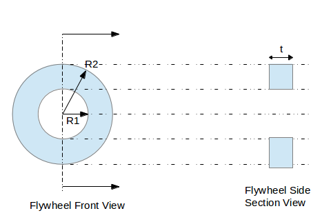
In first part of the flywheel design calculation tutorial example, we saw about calculating required mass moment of inertia for a particular application.
Flywheel design doesn’t stop with that. Its size, shape and material density / mass and maximum stresses are also to be taken into account while designing a flywheel. Which we will discuss in this part.

R1 = Flywheel inner radius
R2 = Flywheel outer radius
Step-1: Material selection
The material of flywheel on most applications will be either cast iron or cast steel.
The Density of the materials (d) is as follows.
Cast iron – 7250 kg/m3
Cast steel – 7800 kg/m3
Step-2: Calculation of the flywheel mass
We already know how to get the mass moment of inertia of a flywheel (I) required for a specific application.
Another equation for calculating the mass moment of inertial (I) is:
I = m* K2
Or, I = m* (R12 + R22)/2………………..eq.2.1
R2 = 400 mm (assumption)
R2= 1.5 * R1 (assumption)………………eq.2.2
Where,
I = Mass Moment of Inertia of flywheel
m = Mass of the flywheel
K = Radius of gyration
R1 = Inner radius of flywheel
R2 = Outer radius of flywheel
From eq.2.1 mass of the flywheel can be calculated, how? Will discuss with the example later.
Step-3: Size and shape calculation
m = π * (R22 – R12 ) * t * d ……………………..eq.2.3
Where,
m = mass (will be obtained from step-2)
d = Density (will be obtained from Step-1)
t = Thickness of the flywheel
From the eq.2.2, 2.3 the cross section, size and thickness of the flywheel can be calculated.
Step-4: Stresses in the flywheel
Maximum stress (tangential) of a flywheel is given by:
Ϭt-max = (d/4)*(ω2)*[(3+v)*R22 + (1-v)* R12]…………..eq.2.4
FOS = ωyield / ω ………….eq.2.5
Where,
Ϭt-max = Max internal stress in the flywheel [ N/m2 ]
d = Density of flywheel material [kg /m3]
ω = Angular velocity of the flywheel [rad/sec]
v = Poisson ratio of the flywheel material
FOS = Design factor of safety
ωyield = Possible angular velocity when maximum internal stress equals to yield stress of the material
Example
Let’s take the same example discussed in Part-1 and find out the mass, size, shape and design parameters as per the equations discussed above.
Solution:
Step-1: density
We will select cast steel for our application, so
Density, d = 7800 kg/m3
Step-2: Mass
From Part-1,
I = 3.43 kg.m2
Using eq.2.1, eq.2.2 and using R1=0.4 m
Mass of flywheel, m= 29.68 kg
Step-3: Size & shape
Outer radius of the flywheel, R2 = 400 mm (given)
From eq.2.2,
Inner radius of flywheel, R1= 266.67 mm
From eq.2.3,
Thickness of flywheel, t=13.62 mm
Step-4: Stresses & FOS
From eq.2.4
Along with flywheel angular velocity from Part-1, as ω=1000 rpm = 2*π*1000/60= 104.67 rad/sec
And assuming Poisson’s ratio, v=0.4
Max. stress in the flywheel, Ϭt-max = 12533445.38 N/m2 = 12.53 MPa
Assuming, Ϭyield = 150 MPa
Max speed at yield stress, ωyield = 362.10 rad/sec
From eq.2.5,
FOS = 362.10 / 104.67 = 3.45
The ωyield gives the critical speed of the flywheel.
This flywheel design and sizing calculation shows how to find out mass, size, cross section, maximum internal tangential stress and factor of safety for a flywheel.

Dear Mr Golpnath
In the formula for size and shape calculations
m = n*(r1^2+r2^2)*t*d
you have shown ‘n’
can you tell me what this represents?
Very kind regards,
Keith Richards.
p.s well done on a thoughtfull method of calculating flywheels.
it’s Pi=22/7
How did you get the speed at yield strength?
Eq.2 is used with Sigma = Yield
Never mind