While driving a vehicle, the speed of the vehicle is not always constant. We will have to apply brakes as and when required. While applying brakes the kinetic energy of the vehicle is reduced.
As we all know that energy can neither be created nor destroyed, the kinetic energy is converted into non-recoverable energy in the form of heat or sound at the brake shoes of the vehicle and is dissipated into the surroundings.
The recovery of this energy wasted during braking will increase the overall efficiency of the engine considerably. Kinetic Energy Recovery System (KERS) is an efficient method of recovering this energy, which would otherwise be wasted.
It comprises of a setup that converts the kinetic energy of the moving vehicle to some other recoverable source of energy such as chemical energy in batteries or inertial energy in a flywheel. There are two types of KERS that are in operation.
Construction of Electrical KERS:
This type of KERS converts the kinetic energy into electrical energy and stored it in batteries for use when required.
It consists of three major components:
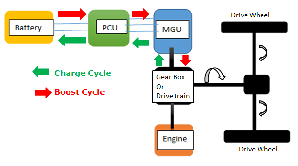
MGU (motor/generator unit): This consists of the rotor coils of the motor and generator wound around the same rotor. They share the same outer field or magnets.
Storage unit: It consists of the batteries for storing the electrical energy. Mostly Lithium ion battery is used for this purpose due to its lower weight and higher power storage capability.
PCU (power control unit): The PCU performs two functions. It inverts and controls the switching between the battery and MGU and it also monitors the status of individual cells in the battery. This is essential because the efficiency of the LI-ion battery cell may decrease leading to battery failure and subsequently rapid overheating, leading to safety issues.

How Electrical KERS System Works
Charge Cycle:
When the brakes are applied, the gearbox output shaft rotates the MGU and it acts as an electrical generator.
The generator produces electrical energy.
The PCU unit transfers the electrical energy to store it in the battery unit.
Boost Cycle:
When the additional acceleration is required, the PCU unit releases the stored electrical energy to the MGU.
The MGU now acts as a motor.
The motor converts the electrical energy to rotational energy.
The kinetic energy is then transferred to the drive wheels through the gear box.
Construction of Mechanical KERS:
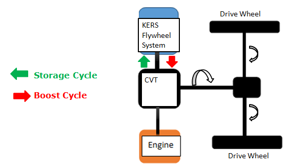
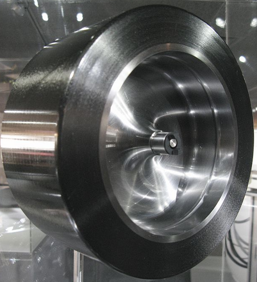
The mechanical KERS systems use high speed flywheel, kept inside a vacuum sealed container, as the energy storage device.
The fly wheel in mechanical kinetic energy recovery system is equivalent to the MGU of the electrical KERS system.
A continuously variable transmission (CVT) is connected between the drive train and the flywheel. Please note, this flywheel is separate from the one that is fitted on engine.
The CVT is used to control the transfer of energy between the KERS flywheel and the drive train.
The CVT is controlled by an electro-hydraulic control system.
The function of the control system is controlling the connection / disconnection of the CVT with drive train and controlling the speed at which the KERS flywheel will rotate.

Working of Mechanical KERS System
Storage Cycle:
In case of braking, the CVT connect the KERS flywheel system with the drive shaft.
The KERS flywheel starts rotating and absorbs kinetic energy from wheels.

Boost Cycle:
As and when there is a requirement for additional acceleration, the flywheel’s kinetic energy get transferred to the wheels again through the CVT.
The electric KERS require a number of energy conversions leading to efficiency losses. Mechanical KERS have a greater efficiency of 70% when compared to the electrical KERS’s 31% efficiency.
The kinetic energy recovery system are used effectively in Formula 1 racing. The energy lost by the car in the curves is stored and is can be used when a boost is required or in straight track. The KERS are also finding their way into passenger cars like RSR variant of Porsche 918.
