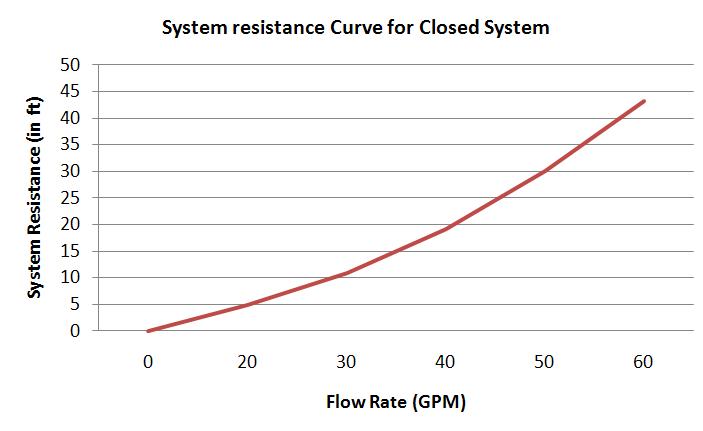
Like pump curve, this is another very important curve for the system designers.
What is a System Resistance Curve?
- This is a graph plotted with flow rate along X axis and the total resistance to the flow along Y axis for fluid handling piping system as well as HVAC fan system.
- For the fluid handling piping system it is often termed as pump system head curve.
- For the HVAC fan system it is often termed as fan system curve.
- Each system has unique resistance or performance curve which is independent of the pump or fan.
- Total system resistance = Frictional resistance + Resistance due to static head (height difference) + Resistance due to pressure head (pressure difference) + Resistance due to velocity (typically neglected)…………………Eq.1
Plotting System Resistance for Closed Hydraulic System
Example Problem: Plot the system resistance curve for the water system which produces 30 ft. (water column) of frictional resistance head for a flow rate of 50 GPM.
Solution:
As a special case, for closed system, the effect of the static head, pressure head and velocity is considered as ZERO. The reason is obvious as the system is closed so no start or end point
Only factor contributing to the system resistance here is the frictional resistance head.
Another rule of thumb: The frictional resistance is proportional to the square of the flow rate.
In the above example it is given that:
Flow rate = 50 GPM
Total system resistance =Frictional resistance =30 ft (water column)
Now let’s create four more data points from the above given data and using the rule of thumb:
Flow rate 1=50*1.2=60 GPM
So, total system resistance 1 = 30*1.2*1.2=43.2 ft.
Flow rate 2=50*0.8=40 GPM
So, total system resistance 2 = 30*0.8*0.8=19.20 ft.
Flow rate 3=50*0.6=30 GPM
So, total system resistance 1 = 30*0.6*0.6=10.8 ft.
Flow rate 1=50*0.4=20 GPM
So, total system resistance 1 = 30*0.4*0.4=4.8 ft.
Now, we have to plot the system resistance curve for the above five points (1 given + 4 derived) by putting the flow rate along the X axis and the total system resistance along the Y axis. The final system performance curve (pump system head curve to be precise) will look like below:

I the next article I will discuss how to see how to do the system curve calculation for an open system.
Hi, I am Shibashis, a blogger by passion and an engineer by profession. I have written most of the articles for mechGuru.com. For more than a decades i am closely associated with the engineering design/manufacturing simulation technologies. I am a self taught code hobbyist, presently in love with Python (Open CV / ML / Data Science /AWS -3000+ lines, 400+ hrs. )
