In the last article, I have discussed how to draw the velocity vector diagram for a four bar linkage mechanism. The same example I will used here as well for explaining the steps required for drawing the acceleration vector diagram for the same mechanism.
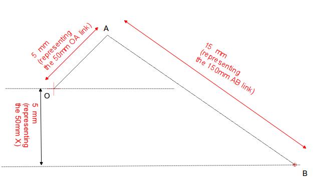
Please go through the example problem before proceeding to this article further. The space diagram of the example problem looks like below:

Before proceeding further, please understand the following fundamental points related to the acceleration diagram of a mechanism:
Funda-1: Typically there will be two components of acceleration, radial and tangential, for any link of a mechanism.
Funda-2: The direction of the radial component of acceleration is always parallel to the orientation of the link.
Funda-3: The direction of the tangential component is always perpendicular to the orientation of the link.
Funda-4: In case the end of a link is moving at a constant angular velocity (i.e., a link hinged at one end and rotating at constant RPM with respect to the hinged point), the moving end will have only radial acceleration component and no tangential component.
Funda-5: In case a joint moves along a straight line (i.e., cylinder), it won’t have any radial acceleration component. The direction of the total acceleration of the joint, in such cases, will be parallel to the line of movement of the joint.
Funda-6: The value of the radial acceleration for a link can be calculated by the following equation:
Axy=XY*(Wxy)^2=(Vxy)^2/XY
Where,
Axy – The radial acceleration of joint X with respect to joint Y.
Wxy – Angular velocity of joint X with respect to joint Y
Vxy – Linear velocity of joint X with respect to joint Y
XY – length of the link XY
Now let’s start drawing the acceleration vector diagram for the above space diagram:
Step-1- orientation of acceleration of link OA: The joint A is rotating at constant angular velocity (of 5000 rpm). So, according to the Funda-4 explained above, the joint A will have only radial component and no tangential component of acceleration. Also, according to the Funda-2, the radial component, in the acceleration vector diagram, will be oriented parallel to the link OA .
Step-2- value of the radial acceleration component for the link OA: From the example problem statement we know the angular velocity of link OA (Wao) = 5000 rpm=523 rad/s and the length of the link OA = 50 mm.
So, by using Funda-6, the radial acceleration component of the link OA can be calculated as:
Arao=50*523^2= 13676450 mm/s2.
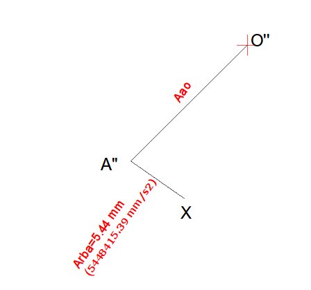
Step-3- Drawing Arao in the acceleration diagram: In order to represent the acceleration vector OA, we have to scale down the value of Arao with suitable scale factor. We will use a scale factor of 0.000001 here. So, the length of the vector Arao will become 13.67 mm in the acceleration vector diagram:

Since, there is no tangential component of acceleration for the link OA, so the Arao will represent Aao, which is shown by the vector O”A” in the above diagram.
Step-4-Drawing radial component of acceleration of joint B with respect to A (Arba) for the link AB: Draw a line starting from the point A” till the point X of the acceleration diagram and oriented along the link AB of the space diagram.
To calculate the value of the Arba, we have to again use the equation of Funda-6:
Arba=(Vba)^2/BA=28587.8^2/150=5448415.39 mm/s2
Where,
the values of Vba and BA can be obtained from the previous article.
The scaled value of the Arba becomes 5.44 mm (remember scale factor = 0.000001).

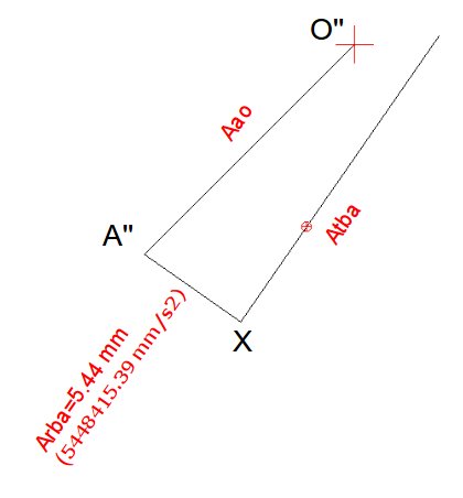
Step-5-Drawing tangential component for the link AB: From the Funda-3 we can say that the tangential component of the acceleration will be perpendicular to the radial component. But, as of now,we don’t know the value of the tangential component (Atba) of acceleration for the link AB.
So, we will start drawing a line from the point X perpendicular to the line A”X:

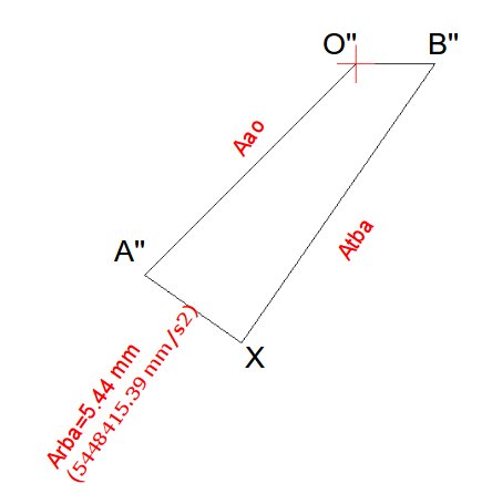
Step-6-Drawing the acceleration vector of the slider B: From the Funda-5, it can be said that the total acceleration of the joint B with respect to the Joint O can be represented by a horizontal line starting from the point O” till the line intersect the line representing the vector Atba:

The Line O”B” represents the total linear acceleration of the slider B with respect to joint-O.
Step-7-Calculating the output acceleration values: The length of the line A”B” and O”B” will represent the linear acceleration of the joint B with respect to the joint A and the linear acceleration of the joint B with respect to the joint O respectively.

By measuring the lengths and dividing by the scale factor, the following values are obtained:
Linear acceleration of joint B with respect to the joint A, Aba=16.7821/0.000001= 16782100 mm/s2
Linear acceleration of joint B with respect to the joint O, Abo=3.6801/0.000001= 3680100 mm/s2
Hi, I am Shibashis, a blogger by passion and an engineer by profession. I have written most of the articles for mechGuru.com. For more than a decades i am closely associated with the engineering design/manufacturing simulation technologies. I am a self taught code hobbyist, presently in love with Python (Open CV / ML / Data Science /AWS -3000+ lines, 400+ hrs. )

Sir, I am not able to understand in which direction A” X is to be made, towards right from A” or left. In this diagram u have made left side of A, but I want to know how u know direction