Properly designed bolted joint is extremely important for striking the balance between the cost and life of the joint.
As a design engineer, for a good bolted joint design, for a given loading conditions and materials of the abutments, you have to basically select the following design parameters:
-
Diameter or size of the bolt or screw
-
Strength of the bolt or screw
-
Preload or tightening torques
-
Selection of the washers
In this tutorial we will discuss about all the design parameters except the selection of washer.
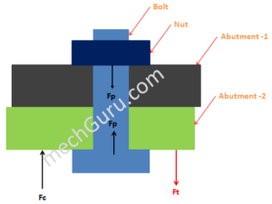
How a Typical Bolted Joint System Works

Fp – Pre load
Fc – Clamping Force
Ft – Tensile load
As you tighten the nut, the preload of the bolt increases, how?
Consider the bolt as a helical tension spring, as you tighten the nut you are actually elongating the spring which then, will try to contact itself to go to its natural position and thus will increase the preload (Fp).
Now, the joint, which is in tension with applied tensile load (Ft), will experience the tensile load (Ft) in the direction opposite to the preload (Fp).
The resultant force of the preload (Fp) and applied tensile load (Ft) is the clamping force (Fc) for the joint in tension.
Fc=Fp – [Kj / (Kb + Kj)]* Ft…………..eq1
Where,
Kj – joint spring rate
Kb – bolt spring rate
Clamping force is responsible for keeping any joint intact.
More the clamping force of a joint better it is…………………………Statement-1
Also, from the equation (eq.1) you can see, as you increase the preload (Fp) the joint will have more clamping force (Fc) for given tensile load (Ft)………………….Statement-2
By combining the Statement-1 &2 above you can conclude that more the preload (Fp) better it is for the joint.
How to increase the preload?
Simple, more the tightening torque you will provide to the bolted joint more preload it will have. The relation between the preload and tightening torque is:
T = K * Fp * d……………………………..eq.3
Where,
T – Tightening torque
Fp – Preload
d – Nominal diameter of bolt
K – Friction factor depends upon abutment materials (mostly varies between 0.15 to 0.3)
But, what is the limit?
Maximum preload or tightening torque you can apply for a bolt is limited by its diameter and the yield strength (or more precisely proof strength) of the bolt materials. How?
Max permissible stress = Fp/(3.14*d*d)……………………….eq.3
We will see in the following example for details.
Example
A bolted joint is subjected to pure tensile load of 10 KN. Calculate the minimum diameter of bolt required.
Assume:
Kj is much much higher than Kb.
Safe stress limit for the bolt material = 650 Mpa
Solution:
From eq.1,
Fc=Fp – [Kj / (Kb + Kj)]* 10………….eq1.1
From the given assumptions, as Kj>>Kb, hence
The quantity [Kj / (Kb + Kj)] =1…………….BC.1
Also, as we need to calculate the minimum bolt size, hence the boundary condition is:
Fc=0………………………………………………BC.2
By applying the BC.1 & BC.2 in the eq1.1,
0 = Fp – 10
Or, Fp=10 KN
So, minimum preload in the bolt, Fp=10 KN.
From eq.3, by applying Max. Permissible stress = safe stress for bolt = 650 Mpa,
650 = 10/(3.14*d*d)
Or, d = 14.28 mm
So for this example we have to select M16 bolt.
Apart from the bolt diameter calculation for tensile application, you also need to calculate thread engagement length for the bolt.
Hi, I am Shibashis, a blogger by passion and an engineer by profession. I have written most of the articles for mechGuru.com. For more than a decades i am closely associated with the engineering design/manufacturing simulation technologies. I am a self taught code hobbyist, presently in love with Python (Open CV / ML / Data Science /AWS -3000+ lines, 400+ hrs. )

Can I understand the Kj and Kb in this way, Kj is the parts spring rate which between the bolt and nut, Kb is spring rate of both bolt and nut. How to get Kj and Kb in the reality?
You are right.
You can use Hook’s law (F=K*x) to calculate spring rate practically
luis cuenca
Please check equation 3 for bolt area
may i know why you neglected the shear force?