A propeller shaft, drive shaft, driveshaft, driving shaft or cardan shaft is used for transmitting torque mainly in automobiles and in ships. This article will discuss the overview of the automobile propeller shaft design calculation.
The following example will be taken as a sample drive shaft design problem throughout this series of article:
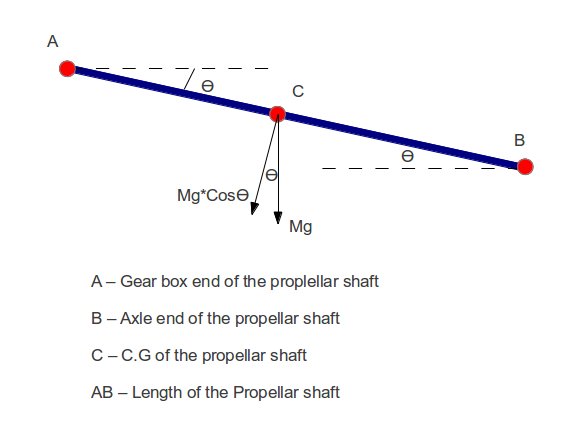
Example problem: Design a cardon shaft with the orientation shown as below:

Given:
Max. Transferred Torque (T)=3500 Nm
Length of shaft (L)=1250 mm
Inclination angle (θ)=2 Deg.
Density (p) =7600 Kg/m3
Yield stress in shear (Ys) =370 Mpa
Rotational speed (N) =6500 RPM
Young’s modulus (E) =207000 Mpa
Shear modulus (G) =80000 Gpa
Solution:
To start with, we will take the diameter of the driving shaft as 50 mm.
The assumed diameter is then will be used as input for the torsional shear stress. The torsional shear stress value should be lesser than the yield strength in shear for the material. In case the calculated shear stress value is more, we have to take the next higher value for the drive shaft and recalculate the torsional shear stress value. The torsional shear stress calculation for the above example problem is discussed in part-2.
The propeller shaft to be further checked for the critical speed to avoid the whirling. The critical speed calculation is discussed in Part-3.
Hi, I am Shibashis, a blogger by passion and an engineer by profession. I have written most of the articles for mechGuru.com. For more than a decades i am closely associated with the engineering design/manufacturing simulation technologies. I am a self taught code hobbyist, presently in love with Python (Open CV / ML / Data Science /AWS -3000+ lines, 400+ hrs. )
