Shear force diagram is the most important first step toward design calculations of structural or machine elements. This article will discuss the steps for drawing shear force diagram.
A design engineer today is much more equipped than she was ever before. She has CAE packages, she has CAD packages, she may have tolerances packages and may be many more. But in order to cross check the output of these packages design engineer should never forget the basics like shear force diagram, bending moment diagram and free body diagram.
Correct shear force diagram (SFD) is very important for designing of machine elements or design of structural members (like truss). Here are simple five steps applicable for drawing almost all types of shear force diagram correctly (Refer the following typical example in connection with the below steps):

1. Draw a horizontal line to represent the beam and divide the line by putting points at the following locations:
– At the point loads locations
– At the beginning and at the end of UDL
– At the reaction locations.
And after that, the above example should look like below:
2. Calculate the reaction forces by using the following basic equations:
ΣFx =0 …………Eqn. 1
ΣFy =0 …………Eqn. 2
ΣM =0 …………Eqn. 3
Where,
ΣFx – Summation of all the horizontal forces
ΣFy – Summation of all the vertical forces
ΣM – Summation of all bending moments
You will get the vertical reactions in case of our example as:
Rc = 60 KN
Re = -20 KN
So, Rc will be acting upward where as Re will be acting downward in our case.
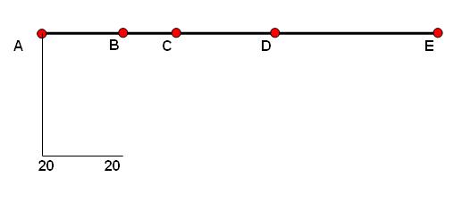
3. Start drawing shear force diagram from any of the extreme ends. Draw a vertical line of same length as the value of applied force at the point. If force acting on the point is downward then the vertical line should go downward or else upward. Suppose we are starting from point A. as force acting at point A in our case is 20 KN downward, so we have to draw a vertically downward line of 20 unit length ( say 20 mm) at point A. It will looks like below:
4. Unless there is an UDL acting a horizontal line to be drawn till we reach the next point on the beam. In our case the shear force diagram will look like below:
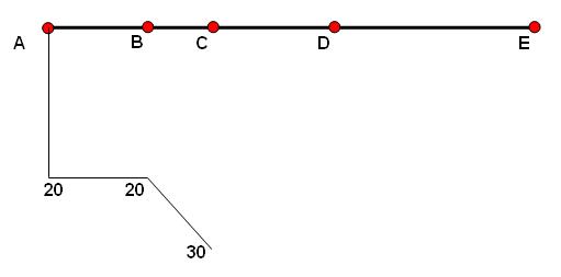
5. See what kinds of load acting on the next point. If it is point load then vertical line from the end point of the already drawn SFD. If UDL is acting up to the next point, then there will be a inclined line. And the slope of the inclination can be calculated as : Force per unit length x Distance.
So, the SFD in our case will become:
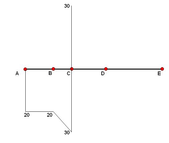
6. Again, in our example vertically upward reaction force of 60 KN is acting at point C. So we have to draw a vertically upward line of 60 unit length (say, 60 mm) there like below:
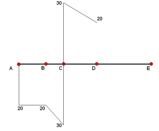
7. Again, between C and D there is a UDL acting downward. So the SFD will become:
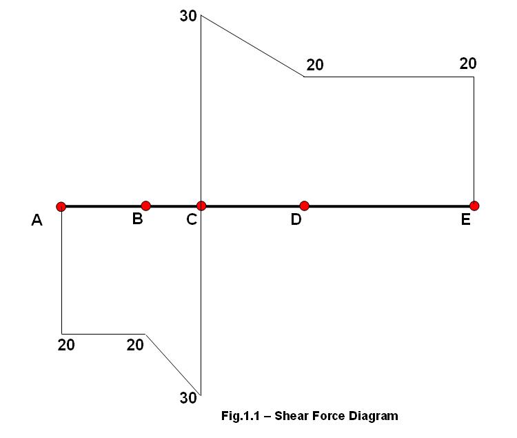
8. In point E of our example vertically downward reaction load of 20 KN is acting. So up to point E there will be a horizontal line further. And at E vertically downward 20 unit length line will be there and the final shear force diagram will look like below:
Drawing correct shear force diagram is very important for a mechanical design engineer. At the location of point load, SFD will go vertically upward or downward depending upon the load direction. In case of UDL acting between two points, shear force diagram line will be inclined and slope can be calculated by multiplying force per unit length with the length between the two points.
Hi, I am Shibashis, a blogger by passion and an engineer by profession. I have written most of the articles for mechGuru.com. For more than a decades i am closely associated with the engineering design/manufacturing simulation technologies. I am a self taught code hobbyist, presently in love with Python (Open CV / ML / Data Science /AWS -3000+ lines, 400+ hrs. )


AMAZING!!!!!!!!!! I UNDERSTAND, THANK YOU THANK YOU THANK YOU!
finally someone that knows hoe to explain these things step by step,so i can understand it…thanx a million
plz send me detail calculation method of shear force diagram. my mail id is rizwankhan_eng@yahoo.com.
Thnx sir
what are the 3 equations in part 2?
Wow! Thanks.. I finally got the hang of it.. 🙂
MOTHER OF GOD. Thanks a million, I’m finally getting this stuff!
MOTHER OF GOD. Thanks a million, I’m finally getting this stuff!
well explained thanks……. but i could not understood how Rc = 60 kN .. ???
well explained thanks……. but i could not understood how Rc = 60 kN .. ???
Rc=60 KN will come from the equations:
sum of all the horizontal forces =0
sum of all the vertical forces =0
sum of all the moment =0
well but i didn’t undershtood hw load is 30 at c & 20 at d
Thanks Suvo
Thanks Suvo
beautiful explanation …..
Brilliant step by step guide for a horiontal beam SFD…Any chance of a step by step SFD for a Three Hinged Portal Frame with a UDL coming in from the side??? Pleeeeease i can work out all the reactions but am struggling to draw its SFD
Brilliant step by step guide for a horiontal beam SFD…Any chance of a step by step SFD for a Three Hinged Portal Frame with a UDL coming in from the side??? Pleeeeease i can work out all the reactions but am struggling to draw its SFD
Please send me a picture of your problem through
http://mechguru.com/main/index.php/contact
Please send me a picture of your problem through
http://mechguru.com/main/index.php/contact
very very helpful! Thanks!
thank you
i like this blog
This blog is the best I´ve seen so far. Went through the shear examples of bolt in embedded concrete for ACI 318 and, although I´m using AS 3600, it helped me heaps. Many thxs for that.
Do you have any software recommendations for precast and tilt-up concrete lifting design calculations ? Nothing fancy, something fast to calculate lifter points, bending moments, maybe pullout capacities of concrete ? Currently using the old Tiltup Max only for bending checking. Thanks