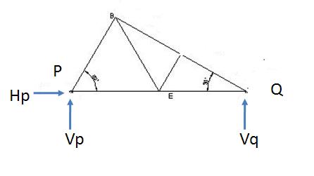
Using free body diagram (FBD) is a method for analyzing and simplifying different forces applied on a member or body. Most of the practical cases you will come across for force analysis are complex in nature. When you will try to put any such problem in paper you will finds loads of information all together. FBD simplifies the problems and you have to make a simple diagram with only those information which plays role in force analysis. Typically you will be having direction and magnitude of forces, critical dimensions and required outline of the body.
- FBD should not be loaded with all the unnecessary dimensions. Unnecessary for the force analysis point of view.
- Actual drawings of members or bodies (on which different forces are applied) are not required, only representation of member will be sufficient.
- FBD should not include the hinges, supports etc., at the locations of hinges, supports suitable reaction forces and moments should be shown.
- When you draw FBD, you should be very clear about which are the bodies need to be included. Usually, the bodies experiencing one or more unknown desired parameters are shown in FBD.
- The boundaries of the included bodies need to be drawn by a simple representation; all surrounding bodies should be considered removed. For example, you want to draw a FBD of a ball lay on the ground; in this case you will draw only a circle to represent the ball along with the required forces.
- All the forces (or reaction forces) from the removed surrounding bodies to the body of your interest needs to be represented at proper place and proper direction in the FBD.
- FBD should show the co-ordinate system.
- The bare minimum information which is required to calculate the values of desired unknown parameters only should be shown in FBD. It shouldn’t be cluttered with all the information of the system.
Plane truss:
Truss is very commonly used in structural engineering. The members can rotate in the joints but all together the whole truss is become stable. Normally for a double support truss, one support is of hinged joint type and another one is sliding type.

Please observe in the above picture, FBD of the whole truss is drawn so the unnecessary member details have not been shown. Also observe the actual reactions at P and Q has been replaced by reaction forces in the FBD. Typically in plane truss, joint at P is of hinge joint type and at Q is of roller (sliding joint type), that is the reason there is no reaction moment at any of these points. We have drawn FBD for the whole truss; similarly you can draw FBD for individual members as well.
Free body diagram is a method of representing practical complex force systems in a simpler way. In FBD the outer boundary/boundaries of the body of interest is represented. Supports of actual body are replaced by suitable reaction forces / moments in FBD.
Hi, I am Shibashis, a blogger by passion and an engineer by profession. I have written most of the articles for mechGuru.com. For more than a decades i am closely associated with the engineering design/manufacturing simulation technologies. I am a self taught code hobbyist, presently in love with Python (Open CV / ML / Data Science /AWS -3000+ lines, 400+ hrs. )

After reading this article my brain “is become” smarterer.
After reading this article my brain “is become” smarterer.