If you are wondering what is stack-up analysis/calculation, the answer is determining worst case scenario. Moreover, the problem can sorted out in early stages of design rather than undergoing prototyping and finding out the issue.
We have already discussed how to do worst case method assembly tolerance stack up calculation for symmetric dimensional tolerances, in this tolerance analysis tutorial we will discuss about non-symmetric tolerances.
A dimension represented on an engineering drawing has nominal dimensions with tolerances. (Ex: 25±0.2). In this simplified example, maximum limit of the part dimension can be upto 25.2mm and minimum can be up to 24.8mm, provided the mating component is designed to cater to this requirement.
Tolerance basis system:
There are certain terminologies associated with tolerance stack up such as basic size, allowance, interference, deviation etc., Let us take a look about the limit system which determines what to change and what to not.
Typically, there are two two limit systems.
1.Basic Hole system
Out of these any one of the system may be adopted.
Both these systems implicate that, tolerances/fits can be obtained by keeping tolerance on one mating surface unchanged while changing the tolerance on the other.
In a basic hole system, the hole dimension is kept unchanged while the tolerance on the shaft is changed and is the case in basic shaft system, keeping the shaft dimension unchanged.
Indian Standard of Limits & Fits include 16 grades of fundamental tolerance. These grades are represented as IT 01, IT02………..IT 16.
Worked out Example:
Let us take a simple example to find out how this is done.
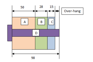
Consider a component which needs to have some overhang (min.3mm) after assembled.
|
Description |
Basic size |
Tolerance |
Maximum |
Minimum |
|
| Max. | Min. | ||||
| A | 50 | +0.3 | -0.5 | 50.3 | 49.5 |
| B | 28 | +0.2 | -0.4 | 28.2 | 27.6 |
| C | 15 | +0.2 | +0.1 | 15.2 | 15.1 |
| D | 98 | +0.5 | 0 | 98.5 | 98 |
| Calculated Overhang Value | 6.3 | 4.3 | |||
Required formulas:
Maximum Overhang of the part = [Max. D – (Min.A + Min.B + Min. C)]
Minimum Overhang of the part = [Min. D – (Max.A + Max.B + Max. C)]
In this case, minimum overhang is the worst-case scenario and which meets our intended length.
This is the simplest way of statistical approach towards Stack-up calculation.
However, stack-up calculations has some shortcomings such as
- Temperautre/Pressure of the part at which it is operayed
- Not taking into account wear & tear
- After assembly deviations/deflections