Do you feel uncomfortable reading those shaft drawings with diameter values followed by the symbols like h8 or g5?
These symbols are combination of fundamental or basic deviation symbol and tolerance grades IT numbers and follows DIN ISO 286 standard. How?
Side Note:
ISO 286 standards is equivalent to other national standard like JIS B 0401, DIN ISO 286, BS EN 20286, CSN EN 20286
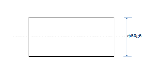
Typically the dimension of a shaft drawing with ISO 286 symbols looks somewhat like below:
How to interpret it?
DIN ISO 286 tolerances calculation of shafts is explained through the following steps.
After following all the steps you should be able to find out the lower tolerance value and upper tolerance value of the shaft or in other word you will convert the g6 symbol of the above example to the numerical upper and lower tolerance values:
Step-1 – Finding the Basic Size: In the figure above, the number followed by the diameter symbol (ɸ) is basic size, i.e. 50.
Step-2 – Reading the fundamental deviation grade: The alphabet following the basic size (50 in the example) is representing the fundamental deviation. In this example the fundamental deviation symbol is g.
Side Note
In simplest term, fundamental deviation tells the starting point of tolerance zone with respect to the basic size. It could be towards negative as well as positive direction with respect to the basic size.
Step-3 – Finding the fundamental deviation value: The fundamental deviation (FD) value for each symbol varies according to the basic sizes of the shaft.
In other words, for the sameFD symbol, the value doesn’t remain same for all the basic sizes of shaft.
Gets the FD value corresponding to the basic shaft size and FD symbol from the ISO 286 fundamental deviation table for shaft.
In the example, from the above table it can be found that for the basic shaft size of 50 mm and the fundamental deviation g the FD value is -10 (minus ten) microns or -0.010 mm.
Step – 4 – Reading the IT tolerance grade: The number followed by the fundamental or basic deviation symbol (g in the example) of the shaft drawing dimension is the tolerance IT grade, 6 in the example we are discussing.
So, in this example shaft tolerance grade is IT6.
Side note
ISO 286 prescribes total 20 IT grades (IT01, IT0, IT1, IT2…IT18) based on the requirements of various production branches based on the accuracy (or tightness of the tolerance zone) of the product. IT01 being the tightest (or narrowest) tolerance zone.
Step – 5 – Finding the tolerance zone size: The value of tolerance zone size corresponding to the basic shaft diameter and the IT grade can be obtained from the ISO 286 tolerance chart.
In this example, with 50 mm basic shaft diameter and IT grade of IT6 the tolerance zone size is 19 microns or 0.019 mm.
Till now you have found the fundamental deviation value or the start of the tolerance zone with respect to basic shaft diameter and the size of the tolerance zone.
So, you can now easily find out the other end of the tolerance zone, right?
Step -6 – Finding minimum and maximum tolerance values:
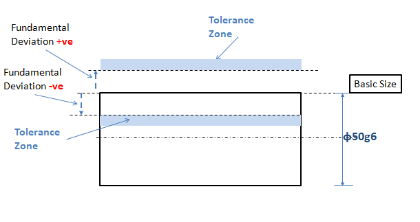
Important rules (refer above figure-2):
- If FD value (calculated from Step-3) is +ve then the FD value will be the lower tolerance limit value.
The tolerance zone size (calculated from Step-5), in such case, to be added with the FD value to get the upper tolerance limit.
- If FD value is –ve then the FD value will be the upper tolerance limit value.
The tolerance zone size (calculated from Step-5), in such case, to be subtracted from the FD value to get the upper tolerance limit.
For the example, using the above two rules:
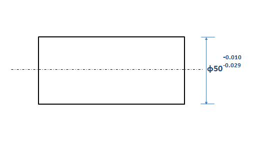
Upper tolerance limit value for the shaft =– 0.010 mm
Lowe tolerance limit value for the shaft = (-0.010 – 0.019) = -0.029 mm
So, the shaft diameter dimension as a result of the tolerance calculation of the shaft as per DIN ISO 286 is:
Hi, I am Shibashis, a blogger by passion and an engineer by profession. I have written most of the articles for mechGuru.com. For more than a decades i am closely associated with the engineering design/manufacturing simulation technologies. I am a self taught code hobbyist, presently in love with Python (Open CV / ML / Data Science /AWS -3000+ lines, 400+ hrs. )